KV-X 系列 × FD-EC 系列 / FD-EP Series
EtherNet/IP™ 連接指南
內容
步驟 1 : 連接所需的裝置
FD-EC 系列/FD-EP 系列


步驟 2 : FD-E 系列的 EtherNet/IP 設定
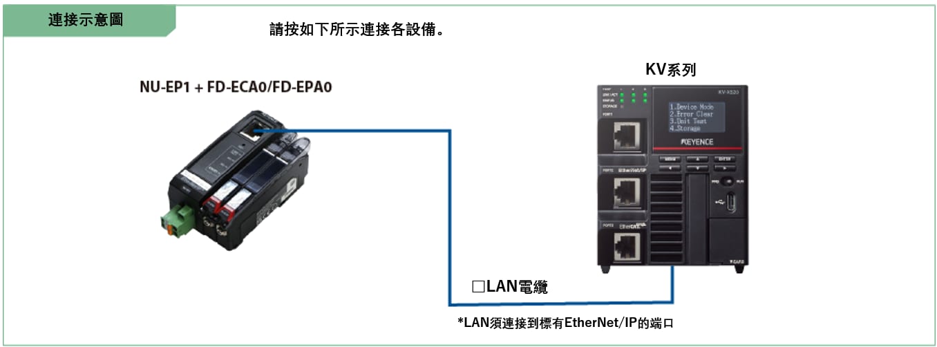
FD-E 系列的 EtherNet/IP 設定設定為 NU-EP1。
如下所示,有兩種 NU-EP1 設定方法可供選擇。
- 從擷取的感測器資訊進行設定
- 手動選擇感應器進行設定
➾ 如果手邊沒有實際的裝置,請在此查看。
本手冊說明使用「從擷取的感測器資訊進行設定」這種容易執行的方法進行的程序。
1. 開啟 KV STUDIO 的單元編輯器,然後按一下 EtherNet/IP 設定圖示。顯示EtherNet/IP設定對話框。
按一下 [手動 (M)]。
* 步驟 2 在需要匯入感測器組態檔案時執行。如果已經匯入感測器組態檔案,請透過 LAN 網路線連接 KV 系列 和感測器裝置,並按一下 [自動配置 (A)],然後進行步驟 3。

2. 在 KV 系列 和傳感器設備透過乙太網路線連接的情況下,在 [EtherNet/IP 設定] 視窗中選擇 [檔案 (F)] ⇒ [自動配置 (S)]。

重點
要執行自動組態,必須滿足下列要求。
- NU-EP1 和 KV 系列使用 LAN 電纜連接。
- 電源供應給 NU-EP1 和 KV 系列。
- 使用乙太網路交換器時,乙太網路交換器以 LAN 電纜連接至 NU-EP1 和 KV 系列,並向乙太網路交換器供電。
3. 當單元編輯器中的組態與實際裝置的組態不同時,會顯示確認專案傳輸的對話框。用 USB 電纜連接 PC 和 KV 系列 後,按一下 [是 (Y)]。
4. 專案傳輸完成後,會顯示 [設備查找設定] 對話框。然後按一下 [查找 (F)]。
從搜尋結果中選擇未指定的 NU-EP1,然後按一下「未分配」。
顯示 [IP 位址設定] 對話框。然後將 NU-EP1 的 IP 位址設定為 「192.168.0.1」,然後按一下 [OK]。
* 如果 IP 位址已被指定,請移至步驟 6。

重點
在 [IP 位址設定] 對話方塊中按一下 ![]() ,可以搜尋未使用過的 IP 位址。
,可以搜尋未使用過的 IP 位址。
步驟 3 : KV-X 系列連接設置
本節介紹如何連接名為 「Vendor Series」 的虛構設備。實際使用時請將「Vender Series」替換為要連接的設備。
重點
對於 CPU 功能版本為 2.0 或更高版本的 KV 系列,可以將變數分配給 EtherNet/IP 的連接。
在 EtherNet/IP 連接上分配變數時,請在“CPU 系統設定”對話框中的“系統設定”的“其他設定”中勾選“更新 Ether-Net/IP 設定時顯示"變數設定"對話框(E)。
通過從“KV STUDIO”功能表中選擇 [ 檢視(V)] ⇒ [CPU 系統設定 (P)] 來顯示“CPU 系統設定”對話框。
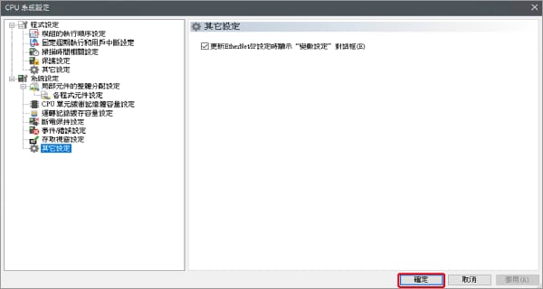
已勾選“更新 EtherNet/IP 設置 設定時顯示"變數設定"對話框(E)”的情況下,在更新 EtherNet/IP 設定並確認設備編輯器的更改內容時,將顯示一個對話框,用於將變數分配給連接。
1. 啟動 KV STUDIO 並創建一個新專案。將支持的機型設置為 "KV-X520",然後點擊 [OK]。
顯示 [確認單元配置設定] 對話框。點擊 [是 (Y)]。

2. 顯示單位編輯器。在「設置單元(2)」選項卡上,點擊 EtherNet/IP 設置的圖示。此時將顯示配置類型選擇對話框。點擊 [手動 (M)]。

3. 在「單元設置 (2)」選項卡中,設置 KV-X 系列的 IP 位址。在此範例中配置設置如下所示。
* 需要執行Step4以導入感測器設置檔案。導入感測器設置檔案後,請繼續執行Step5。

4. 選擇 [EDS 檔案(D)] → [登錄(I)] 以導入Keyence的感測器設定檔案(ez1檔案)或 EDS檔案。
* 從Keyence網站下載感測器設定檔案。

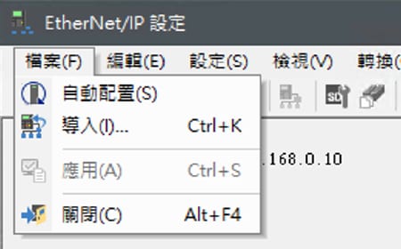
5. 使用乙太網電纜連接 KV-X 系列和 EtherNet/IP 設備後,在 [EtherNet/IP 設定] 視窗中選擇 [檔案(F)] → [自動配置(S)]。
6. 當單元編輯器上的配置與實際設備的配置不同時,會顯示一個確認專案傳輸的對話框。使用USB電纜連接PC和 KV-X 系列後,點擊 [是(Y)]。
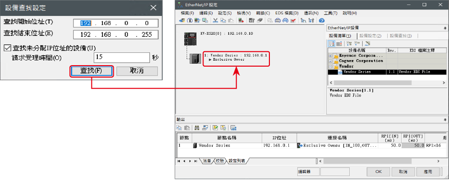
7. 專案傳輸完成後,顯示 [設備查找設定]對話框。然後點擊 [查找 (F)]。自動配置完成後,將自動添加 「Vendor Series」。然後點擊 [OK] 關閉 [EtherNet/IP 設置] 視窗。
8. 點擊[OK]以退出單位編輯器。
重點
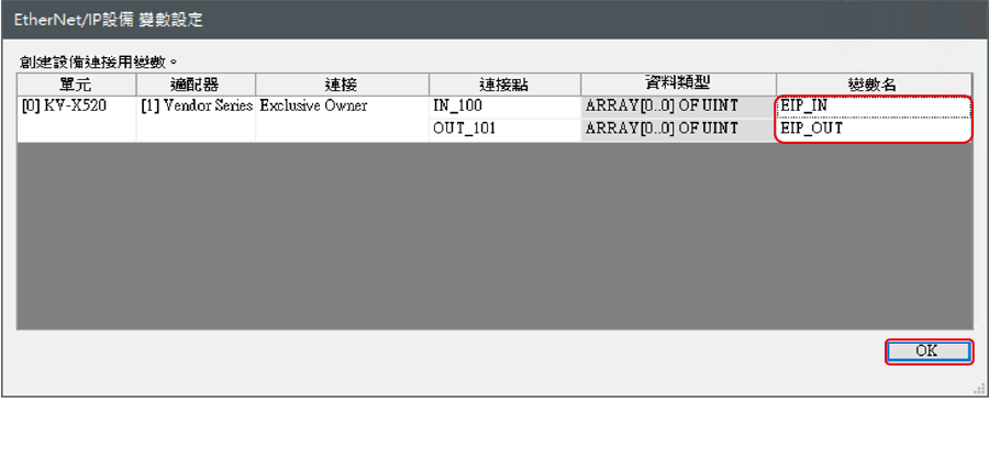
當選中“更新 EtherNet/IP 設置 (E) 時顯示“變數設置”對話框”時,將顯示 [EtherNet/IP 設備變數設定] 對話框。
輸入分配給連接的變數名稱,然後按下 [OK]。
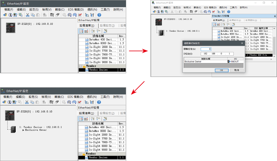
- 手動設置設備配置的方法
在“EtherNet/IP 設定”的 [設備清單 (1)] 選項卡中,拖放“Vender Series”並創建設備配置。
傳輸和監控設置數據
1. 從功能表中選擇 [監控器/模擬器(N)] > [ PLC傳輸 →監控器模式 (C)]。
在 [PLC傳輸] 對話框中,點擊 [執行(E)]。
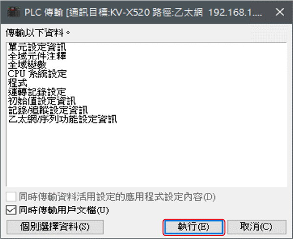
2. 如果在傳輸數據之前和之後都顯示以下對話框,請兩次點擊 [是(Y)]。

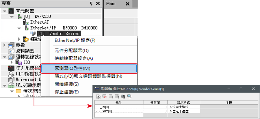
3. 右鍵點擊工作空間中的“Vender Series”,然後選擇 [感測器IO監控(M)]。
可以輕鬆監控感測器的資訊。
重點
還可以通過啟動即時時序圖監視器在波形圖上檢查資訊。
右鍵按下「感測器 I/O 監視」並選擇 [即時時序圖監控器(H)]。
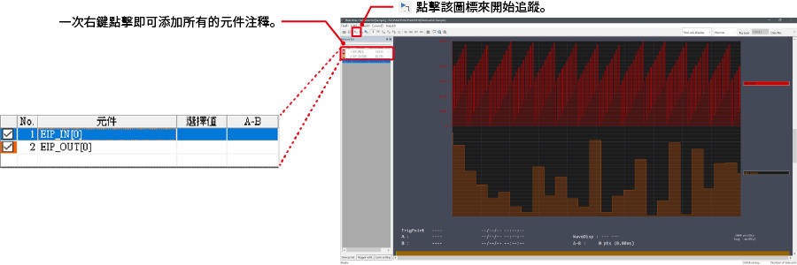
不需要調整範圍,因為即時時序圖監控器會自動執行縮放。
如何通過程式來操作參數
從而更改設定值
感測器的設定值可透過以下兩種方法更改:
A : 從PC更改
B : 從階梯圖程式更改
* 以下將以感測器MU-N(FD-0*C)為例進行說明。
A : 從 PC 更改
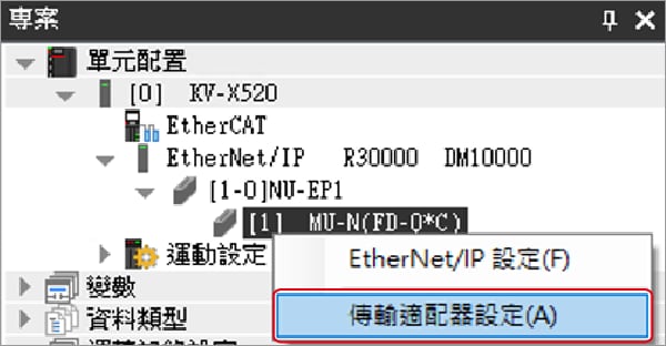
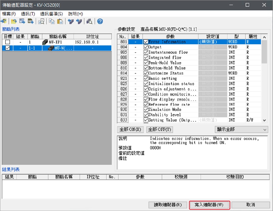
要從 PC 更改設置,請使用 KV STUDIO 中的傳輸適配器功能。
1. 在工作空間中展開單元配置。右鍵點擊「MU-N(FD-0*C)」並選擇 [傳輸適配器設定 (A)]。
2. 在「MU-N(FD-0*C)」的對應參數上打勾,然後輸入設定值。
點擊 [寫入適配器 (W)] 將設定值寫入感測器。
*要讀取感測器的設置值,請選擇 [讀取適配器 (R)]。
B : 從階梯圖程式更改
透過階梯圖程序,使用顯示報文通訊來更改設置值。
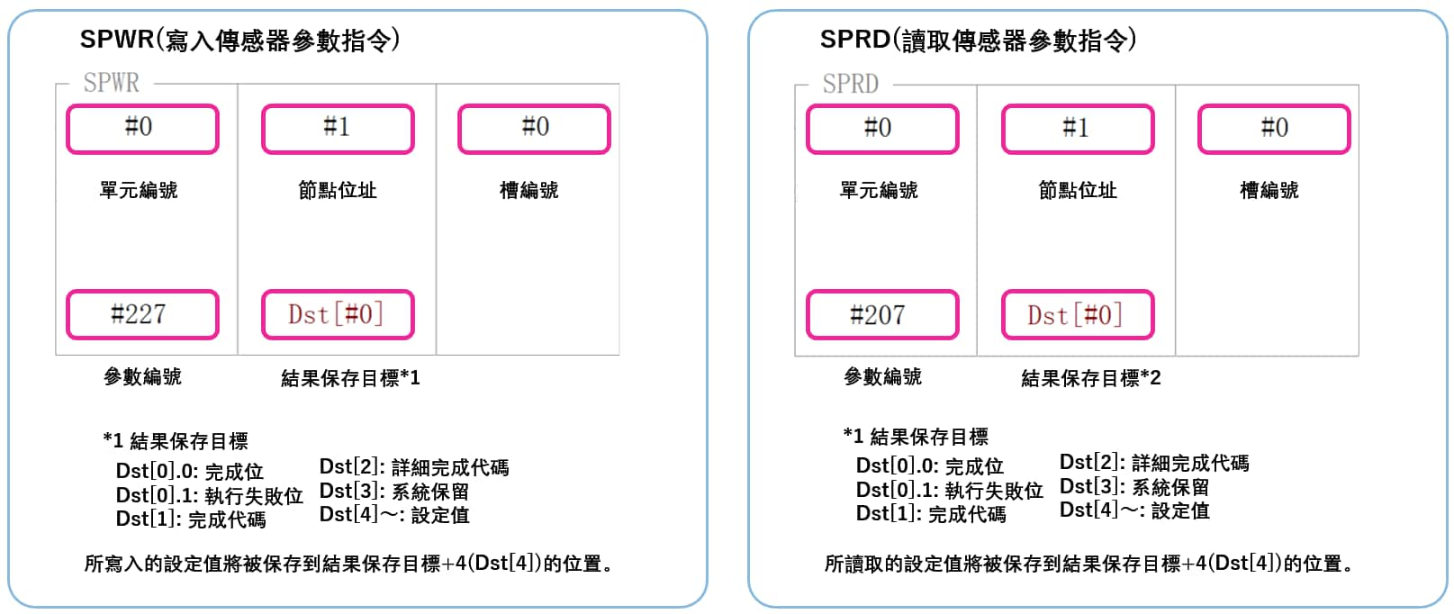
要使用 KV STUDIO 執行顯示報文通訊,請使用感測器設定指令(SPWR [感測器參數寫入] 和 SPRD [感測器參數讀取])。

1. 在編輯器模式下,創建一個階梯圖程式,如下所示。
* 有關參數編號,請參閱參數清單。

2. 傳輸階梯圖程式。
3. 當 MR100 處於ON狀態時,設置值會被改寫。
* 將設定值存儲在 DM4 中([結果存儲位置] + 4)。
重點
RT(即時)編輯功能
當您使用階梯圖程式時,您可以直接將元件註釋或參數名稱輸入到自動搜索並顯示輸入候選項。

補充 : 記憶體映射
FD-EC 系列/FD-EP 系列 [EtherNet/IP] 設定
以下是循環通訊和訊息通訊中可交換的參數清單。
▶ 可在循環通訊中取得的參數清單
由於在循環通訊中可獲得的參數會在 KV 系列與 FD-E 系列之間以固定的內部自動更新,因此不需要讀寫資料的程式。以下為分配給變量時的記憶體映射。
FD-E 系列 → KV 系列
| Member Name | Data Type | Detail |
|---|---|---|
| NU_ErrStatus | BOOL | NU-EP1 Error Status |
| UpdateSensorSetting | BOOL | Updating Sensor Setting |
| SensorEEPROM_Busy | BOOL | Sensor EEPROM Busy |
| SensorExtIn_Busy | BOOL | Sensor External Input Busy |
| SensorSettingErr | BOOL | Sensor Setting Error |
| SensorReady | BOOL | Sensor Ready |
| WarningStatus | BOOL | Warning Status |
| ErrStatus | BOOL | Error Status |
| Error | ARRAY[0..15] OF BOOL | Error |
| Warning | ARRAY[0..15] OF BOOL | Warning |
| OutputCondition | ARRAY[0..15] OF BOOL | L-on/D-on (N.O./N.C.) |
| CurrValOverRange | ARRAY[0..15] OF BOOL | Current Value Over Range |
| CurrValUnderRange | ARRAY[0..15] OF BOOL | Current Value Under Range |
| CurrValInvalid | ARRAY[0..15] OF BOOL | Current Value Invalid |
| Output | ARRAY[0..15] OF BOOL | Output |
| ExtInResp | ARRAY[0..15] OF BOOL | External Input Response |
| ErrID_Number | UINT | Error ID Number |
| ErrCode | UINT | Error Code |
| WarningID_Number | UINT | Warning ID Number |
| WarningCode | UINT | Warning Code |
| SettingErrID_Number | UINT | Setting Error ID Number |
| CurrValue | ARRAY[0..15] OF UINT | Current Value |
| SettingValue1 | ARRAY[0..15] OF UINT | Setting Value 1 |
| SettingValue2 | ARRAY[0..15] OF UINT | Setting Value 2 |
| Reserved | UINT | |
| FastOutput | ARRAY[0..15] OF BOOL | Fast Output |
KV 系列 → FD-E 系列
| Member Name | Data Type | Detail |
|---|---|---|
| ExtInRequest | ARRAY[0..15] OF BOOL | External Input Request |
| Reserved | UINT |
▶ 訊息通訊中可取得的參數清單
訊息通訊是在任意時間交換資料時使用的通訊方法,例如設定值的變更。訊息通訊需要梯形圖程式來進行通訊。然而,KV 系列也可以使用專用指令字 (SPWR/SPRD 指令) 與 KEYENCE 感測器進行通訊。
| Attribute ID | Parameter No. | Clamp-on_FD-ECA0 | Dual_FD-EPA0 |
|---|---|---|---|
| 800 | - | Number of Group 1 entries | Number of Group 1 entries |
| 801 | 801 | Error information | Error information |
| 802 | - | - | Warning information |
| 803 | - | - | Warning function |
| 804 | 804 | Output | Output |
| 805 | 805 | Current value (Flow) | Current value (Flow) |
| 806 | - | - | Current value (Pressure) |
| 807 | - | - | Current value (Seating) |
| 808 | 808 | Current value (Accumulated) | Current value (Accumulated) |
| 809 | 809 | Peak-hold value (Flow) | Peak-hold value (Flow) |
| 810 | 810 | Bottom-hold value (Flow) | Bottom-hold value (Flow) |
| 811 | - | - | Peak-hold value (Pressure) |
| 812 | - | - | Bottom-hold value (Pressure) |
| 815 | 815 | Slide switch status | Slide switch status |
| 816 | - | - | Application current value 1 |
| 817 | - | - | Application current value 2 |
| 818 | - | - | Application current value 3 |
| 819 | 819 | Diagnostic info | Diagnostic info |
| 824 | 824 | Init settings finished | Init settings finished |
| 825 | 825 | Initialization status | Initialization status |
| 826 | 826 | Flow origin adjustment status | Flow origin adjustment status |
| 827 | - | - | Application learning status |
| 832 | - | Number of Group 2 entries | Number of Group 2 entries |
| 833 | 833 | OUT1 Set/Lower limit val. | OUT1 Set/Lower limit val. |
| 834 | 834 | OUT2 Set/Lower limit val. | OUT2 Set/Lower limit val. |
| 836 | 836 | OUT1 Upper limit val. | OUT1 Upper limit val. |
| 837 | 837 | OUT2 Upper limit val. | OUT2 Upper limit val. |
| 838 | 838 | OUT1 Set/Lower limit val.(Flow) | OUT1 Set/Lower limit val.(Flow) |
| 839 | 839 | OUT2 Set/Lower limit val.(Flow) | OUT2 Set/Lower limit val.(Flow) |
| 840 | 840 | OUT1 Upper limit val. (Flow) | OUT1 Upper limit val. (Flow) |
| 841 | 841 | OUT2 Upper limit val. (Flow) | OUT2 Upper limit val. (Flow) |
| 842 | - | - | OUT1 Set/Lower limit val.(Prs.) |
| 843 | - | - | OUT2 Set/Lower limit val.(Prs.) |
| 844 | - | - | OUT1 Upper limit val. (Prs.) |
| 845 | - | - | OUT2 Upper limit val. (Prs.) |
| 846 | 846 | OUT1 Lower val. (Accumulated) | OUT1 Lower val. (Accumulated) |
| 847 | 847 | OUT1 Upper val. (Accumulated) | OUT1 Upper val. (Accumulated) |
| 848 | 848 | OUT2 Lower val. (Accumulated) | OUT2 Lower val. (Accumulated) |
| 849 | 849 | OUT2 Upper val. (Accumulated) | OUT2 Upper val. (Accumulated) |
| 864 | - | Number of Group 3 entries | Number of Group 3 entries |
| 865 | 865 | Key Lock Status | Key Lock Status |
| 866 | 866 | Key Lock PIN code | Key Lock PIN code |
| 868 | 868 | Output logic | Output logic |
| 869 | 869 | Key Lock Method | Key Lock Method |
| 871 | 871 | Response time (Flow) | Response time (Flow) |
| 872 | - | - | Response time (Pressure) |
| 873 | 873 | Flow unit | Flow unit |
| 874 | - | - | Pressure unit |
| 875 | 875 | Tube material | - |
| 876 | 876 | Select Tube I.D. Setting | - |
| 877 | 877 | Tube inner diameter | - |
| 878 | 878 | Flow direction | Flow direction |
| 879 | 879 | Flow rate span adjustment | Flow rate span adjustment |
| 896 | - | Number of Group 4 entries | Number of Group 4 entries |
| 897 | 897 | OUT1 function | OUT1 function |
| 898 | 898 | OUT2 function | OUT2 function |
| 900 | 900 | OUT1 detection mode | OUT1 detection mode |
| 901 | 901 | OUT2 detection mode | OUT2 detection mode |
| 903 | 903 | IN1 function | IN1 function |
| 904 | - | - | IN2 function |
| 905 | 905 | Pulse weight (Accumulated) | Pulse weight (Accumulated) |
| 906 | 906 | Accumulated flow reset method | Accumulated flow reset method |
| 907 | 907 | Auto hold time | Auto hold time |
| 908 | 908 | Zero cut flow rate | Zero cut flow rate |
| 909 | 909 | Gas type selection | Gas type selection |
| 910 | 910 | Specific heat ratio | Specific heat ratio |
| 911 | 911 | Average molecular weight | Average molecular weight |
| 928 | - | Number of Group 5 entries | Number of Group 5 entries |
| 929 | - | - | OUT1 Set/Lower limit val.(Seat.) |
| 930 | - | - | OUT1 Upper limit val. (Seating) |
| 931 | - | - | Seating pressure lower limit |
| 932 | - | - | Seating pressure upper limit |
| 933 | - | - |
Span adjustment value (seating
confirmation) |
| 935 | 935 | OUT 1 hysteresis(Flow) | OUT 1 hysteresis(Flow) |
| 936 | 936 | OUT 2 hysteresis(Flow) | OUT 2 hysteresis(Flow) |
| 937 | - | - | OUT1 hysteresis (Pressure) |
| 938 | - | - | OUT2 hysteresis (Pressure) |
| 939 | - | - | OUT1 hysteresis (Seating) |
| 943 | - | - | Averaging count |
| 944 | 944 | Simulation mode | Simulation mode |
| 945 | 945 | Simulation value (Flow) | Simulation value (Flow) |
| 946 | - | - | Simulation value (Pressure) |
| 947 | 947 | Blink head LED | Blink head LED |
| 948 | 948 | Zero flow input | Zero flow input |
| 949 | - | - | Application selection |
| 950 | - | - | Application set value 1 |
| 951 | - | - | Application set value 2 |
| 952 | - | - | Application set value 3 |
| 953 | - | - | Application operate setting |
| 955 | - | - | Operate threshold (Flow) |
| 956 | - | - | Operate threshold (Pressure) |
| 957 | - | - | Operate sensitivity |
| 960 | - | Number of Group 6 entries | Number of Group 6 entries |
| 961 | 961 | Flip display | Flip display |
| 962 | 962 | Hold screen display selection | Hold screen display selection |
| 963 | 963 | Indicator mode | Indicator mode |
| 965 | 965 | Display averaging | Display averaging |
| 966 | 966 | Current Display | Current Display |
| 968 | 968 | Display Brightness | Display Brightness |
| 969 | 969 | Display resolution (Flow) | Display resolution (Flow) |
| 970 | 970 |
Display resolution (Accumulated) |
Display resolution (Accumulated) |
| 971 | - | - | Display resolution (Pressure) |
| 975 | 975 | Language | Language |
| 992 | - | Number of Group 7 entries | Number of Group 7 entries |
| 994 | 994 | Tag String | Tag String |
| 1003 | 1003 | Flow conversion | Flow conversion |
| 1004 | 1004 | Reference temperature | Reference temperature |
| 1005 | 1005 | Pressure to use | - |
| 1007 | 1007 | Tuning target | Tuning target |
重點
執行 SRWR(感測器參數寫入指令)或 SPRD(感測器參數讀取指令)時,會寫入或讀取指定的感測器參數。
